
4 Common Mistakes Made Reading GD&T
by Kyle Zachary, MSOL, Continuing Education Instructor, Goodwin University
Geometric dimensioning and tolerancing (GD&T) is used for defining part geometry and dimensions. A basic understanding of GD&T is essential for anyone who works with technical drawings. Through the years of teaching GD&T to workers through Goodwin University’s Continuing Education programs, we have observed some recurring misconceptions that are common among workers trying to interpret drawings. We teach these concepts in our workshops and are always available to answer other questions about GD&T and other training topics.
The tolerance value in a feature control frame is bilateral.
Actually, the tolerance value is expressing the width between the parallel boundaries of the tolerance zone (see the drawing in the last bullet), or the size of the circular or square zone in the case of true position. Bilateral tolerance is applied to dimensional tolerances only. So, the 0.2mm tolerance shown above in the feature control frame describes the total limit of the tolerance, not + 0.2/-0.2 as with a dimensional tolerance.
Basic dimensions have a general dimensional tolerance (found in the title block) applied to them.
Basic dimensions, identified by the frame around them, do not have dimensional tolerances applied to them; they are indirectly toleranced by a geometric tolerance that is being applied to the dimensioned feature:
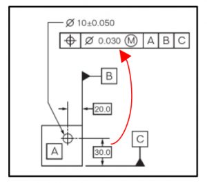
In the example above the 30.0 and 20.0mm positional dimensions, both in frames that indicate a basic dimension, are being indirectly tolerance by the true position tolerance in the control frame at the top of the drawing.
Flatness and parallelism measure the same thing and can be tested the same way.
Actually, flatness controls the geometry of a feature relative to itself; the tolerance zone condition is not influenced by other features on the part. The feature’s flatness is tested relative to that feature. Parallelism requires a reference, or datum, from which the parallelism of the specified feature is determined:
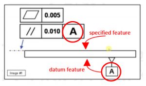
So, in the drawing above, the top plane of the part or the specified feature must have datum reference plane from which to assess its parallelism, in this case datum “A”.
The tolerance value in an angularity tolerance is expressed in degrees.
While a traditional dimensional tolerance for an angular feature is typically expressed in degrees, this is not the case for a geometric angularity tolerance. As with most other geometric tolerances, the tolerance value is simply expressing the distance between the parallel boundaries of the tolerance zone and will be expressed in inches or millimeters. The tolerance zone is theoretical and assumed to be oriented at precisely the specified angle of the feature:
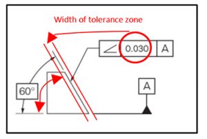
It is counter-intuitive and even disconcerting to think about limiting an angular specification with dimensional units such as inches or millimeters. Once we understand that the tolerance value in the feature control frame simply describes the width of a tolerance zone, this should be clearer.
We hope that this review has been informative and helpful to you when reading GD&T. Please feel free to contact us with questions about any of our training topics.
Click here to learn more about Goodwin’s Continuing Education and Manufacturing Worker Training Programs.
Kyle Zachary is a faculty member in Goodwin University’s School of Business, Technology, and Advanced Manufacturing. He has worked in the wood technology industry and financial markets. Kyle has been a full-time teacher for 10 years, teaching a diverse range of subjects from ESL to Manufacturing and Six Sigma, including teaching positions in the U.S. and Brazil.
kzachary@goodwin.edu